Industrial Polymer 3D Printing Review: Our engineers compared voxeljet HSS, HP MJF, and SLS
The market for polymer 3D printing is rapidly growing, with reports that polymer powder consumption grew by 43.3{64d42ef84185fe650eef13e078a399812999bbd8b8ee84343ab535e62a252847} throughout 2021, overtaking photopolymer resins as the most used 3D printing material. As such, competition between industrial 3D printer OEMs is fiercer than ever, giving manufacturing firms ample choice with technologies such as High Speed Sintering (HSS), Multi Jet Fusion (MJF), and Selective Laser Sintering (SLS).
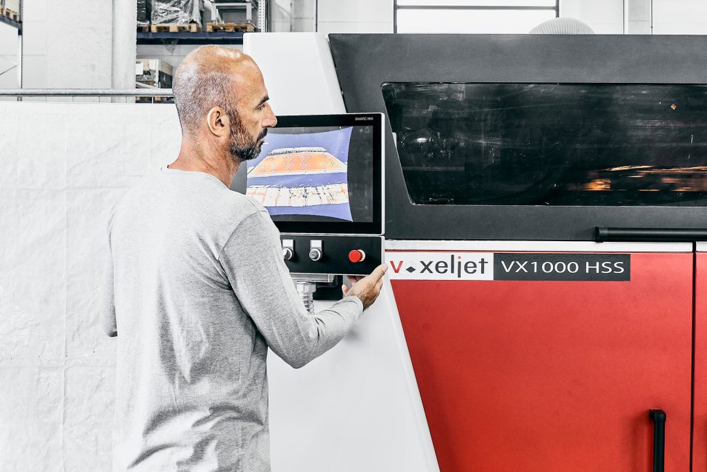
Originally invented by Neil Hopkinson at the University of Loughborough and Sylvia Monsheimer at Evonik at the same time in the early 2000s, HSS is a powder-based 3D printing process similar to binder jetting. It’s known for its fast print speeds and large part production capabilities. Since obtaining a license to commercialize the technology in 2016, voxeljet has developed its own version of HSS and launched its first HSS 3D printer back in 2017. The firm has since packed out its product portfolio with several HSS-powered 3D printers such as the VX200 HSS and VX1000 HSS.
Similarly, MJF is a sibling under the binder jet banner. HP offers engineering-grade polymer parts for both functional prototyping and end-use production, seeing use in industries such as automotive and consumer goods.
Unlike HSS and MJF, which are inkjet-based processes, SLS is a form of laser powder bed fusion. The approach utilizes a high-power laser beam, together with a scanning system, to 3D print parts in a bed of polymer powder.
Since all processes feature similar properties and surface finishes, it’s not uncommon for these polymer printing technologies to be seen as competitors. In this special edition review, we’ll run through the ins and outs of these three technologies and see how they differ from one another.
The ink-jetting battle: HSS vs MJF
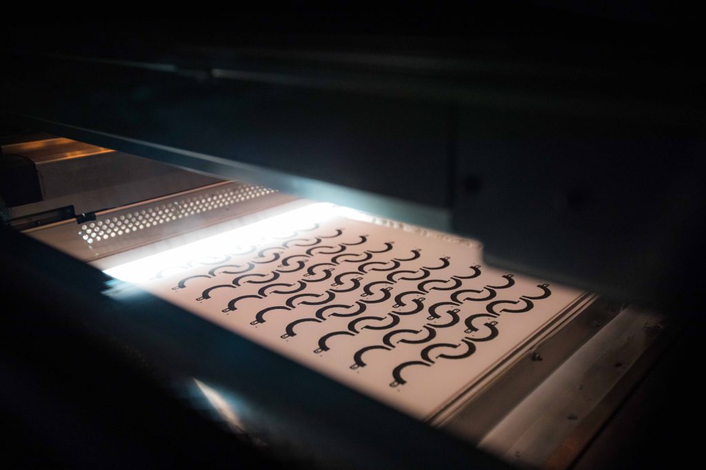
So how does HSS work? It starts off by applying a thin layer of polymer powder to a heated build platform. An inkjet printhead then moves across the platform and jets an infrared-reactive ink to select areas of the powder bed. Once exposed to IR light, the ink-infused powder absorbs the heat, sintering and fusing it into a solid layer, leaving the unprinted areas as loose powder. The build platform is then lowered, a fresh layer of powder is deposited, and the process repeats itself layer-by-layer until the 3D part is printed.
MJF is similar to HSS in many ways. Much like the HSS process, MJF involves jetting a radiation-absorbing fluid (aka the fusion agent) to certain areas of a bed of polymer powder. The borders of the other areas, which aren’t to be printed, are cooled with a secondary fluid called the detailing agent. Once the jetting is complete, an IR lamp is used to radiate the entire build area, fusing the sections doused in the binding agent. The borders jetted with the detailing agent remain unfused.
Apart from the huge size of voxeljet’s VX1000 printer, the primary difference between the two technologies is in the number of fluids used. A second cooling agent isn’t necessary with HSS because voxeljet’s 3D printers can control the temperatures of the bound and unbound powder materials independently of each other. They do this via the use of two different IR emitters with different wavelengths, meaning the detailing agent isn’t required to achieve a precise edge definition.
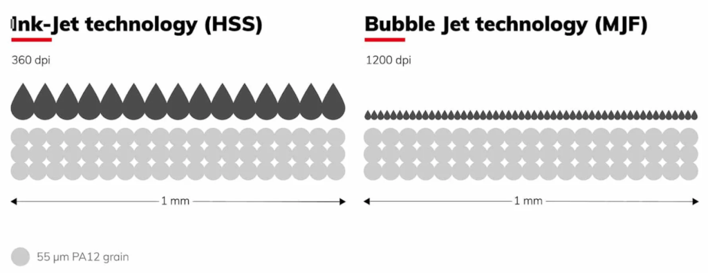
Thanks to its detailing agent, MJF boasts resolutions of 1200dpi while HSS only sports 360dpi. But the key factor in determining part resolution is still the grain size of the powder, so a higher printhead resolution doesn’t necessarily mean a more precise part in this case. In fact, since HSS droplets are slightly larger than individual polymer grains (which are typically ~55 microns wide), they’re able to completely cover the intersections between grains, which is crucial for sintering to take place.
Looking at some of the key tech specs, MJF systems have a maximum build volume of 380 x 294 x 380mm, while the voxeljet VX1000 HSS features a hearty 1000 x 540 x 180mm (for PA12). The VX1000 HSS also holds its own when it comes to print speed, sitting at a rapid 7300cm³/h. On the other hand, the most productive MJF 3D printers offer print speeds of 5058cm³/h.
Another major difference between the two processes is HSS’ open-source approach to 3D printing. voxeljet customers are able to freely access all of the process parameters of their machines, adapting their builds to their own materials without any hindrance. This can lead to significant cost savings as users negotiate their own powder prices with material suppliers directly. The list of compatible polymers is a long one and includes PA12, TPU, and PP, which are either commercially available or soon to be available. Additionally, successful proof of concepts include PA613, PEBA, and EVA.
By contrast, MJF 3D printers are able to process PA12, PA11, and PP. Both technologies allow for unprinted powder materials to be recycled and reprocessed.
Adding SLS 3D printing into the mix
For the sake of comprehensiveness, we’ll also be covering SLS 3D printing in this review.
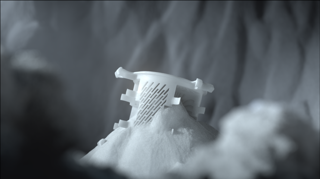
SLS 3D printers work like so: a laser initially scans a 2D cross-section of the first layer of the part into the powder bed, which doesn’t quite melt the powder but sinters it enough for it to fuse together into a solid layer. Once the first layer is complete, the build platform moves down, prompting the recoater to spread a thin, uniform layer of material over the existing powder bed. This cycle of printing and recoating repeats itself until the entire build has been fabricated.
The largest SLS systems can print parts in the meter range, with Z-height print speeds of around 48mm/h (depending on box utilization).
The powder bed fusion ecosystem is one of the most developed in the 3D printing industry, meaning today’s industrial-grade SLS systems are compatible with all manner of polymer powders. This includes PA6, PA11, PA12, TPU, PP, PAEK, PEEK, and many more.
HSS vs MJF vs SLS: mechanical performance
To evaluate the mechanical performance of each 3D printing technology, we looked at some tensile testing data provided to us by a range of suppliers. The data covers a total of 15 tensile test dogbone specimens for each technology (five printed along the X-axis, five along the Y-axis, and five along the Z-axis), each 3D printed in PA12 and tested under ISO 527 standards.
First, to determine which of the polymer printing technologies produces the strongest parts, we look at the average ultimate tensile strength (UTS). This is the maximum pulling stress a part can withstand before breaking. For this round, it was SLS that printed the highest strength specimens on average (45.17MPa), followed by MJF (43.10MPa), and then HSS (40.60MPa). The corresponding maximum load at break for the three technologies were 1885.01N, 1782.7N, and 1659.1N respectively.
It’s interesting to note that in voxeljet’s official PA12 data sheet, the UTS values are 52 (+/- 1) MPa for XY and 46 (+/- 2) MPa for Z. The reason for the discrepancy is that the data given in the material data sheet refers to prints with process parameters optimized for mechanical data. By contrast, the dogbones printed for this study were printed with parameters optimized for precision and detail. Customers can therefore choose to have parts printed with specs optimized for their own applications, tying into the open-source strategy offered by voxeljet.
Next up is the Young’s Modulus, which is a measure of tensile stiffness. A higher Young’s Modulus means a stiffer part that deforms only slightly under elastic loads, whereas a lower Young’s Modulus corresponds to a more elastic part that’s flexible under load. This time around, it was HSS that yielded the stiffest parts (1.82GPa), followed by SLS (1.73GPa), and MJF (1.43GPa).
Finally, we have the elongation at break, which is a measure of ductility. The measurement shows how much a part can be stretched, as a percentage of its original length, before it fractures. Interestingly, in the XY plane, it was SLS that printed the most ductile parts (17.53{64d42ef84185fe650eef13e078a399812999bbd8b8ee84343ab535e62a252847}), followed by MJF (16.87{64d42ef84185fe650eef13e078a399812999bbd8b8ee84343ab535e62a252847}), and HSS (8.88{64d42ef84185fe650eef13e078a399812999bbd8b8ee84343ab535e62a252847}). However, in the Z-plane, MJF produces the most ductile parts (14.40{64d42ef84185fe650eef13e078a399812999bbd8b8ee84343ab535e62a252847}), followed by SLS (9.32{64d42ef84185fe650eef13e078a399812999bbd8b8ee84343ab535e62a252847}), and HSS (6.36{64d42ef84185fe650eef13e078a399812999bbd8b8ee84343ab535e62a252847}).
HSS vs MJF vs SLS: dimensional precision
Next up, we wanted to compare the dimensional precision of each 3D printing technology. To do this, we took metrology scans of four different part geometries, each of which was 3D printed and scanned three times (once via HSS, MJF, and SLS). We compared these 12 scans of the parts to the original STL files, which allowed us to calculate the deviations and inaccuracies of the prints at various points across their surfaces. The 3D scanner used was a GOM ATOS II 400, which is precise to ±30μm.
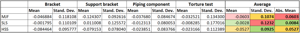
Looking at the metrology data, it’s the four SLS printed parts that were the most precise overall, seeing as their dimensions were the closest to the intended dimensions of the STL models with an average offset of just 0.0084mm. HSS weighed in with an average imprecision of 0.0527mm, while MJF lagged further behind at 0.0603mm.
The mean alone doesn’t tell the whole story, however. Looking at the standard deviation values of the dimensional inaccuracies, SLS actually had the highest spread at 0.1232mm. This was followed by MJF at 0.1074mm, while HSS had the lowest spread between its scanned inaccuracies at just 0.0925mm. So, while SLS printed parts’ dimensions will on average be truer to size, it’s actually the HSS process that offers the greatest consistency and repeatability.
To put this into context, we’ll take a closer look at one of the four geometries (the support bracket), which is shown above. The bounds on the bell curves define the area where 99.6{64d42ef84185fe650eef13e078a399812999bbd8b8ee84343ab535e62a252847} of the points are located. For example, 99.6{64d42ef84185fe650eef13e078a399812999bbd8b8ee84343ab535e62a252847} of the dimensions 3D printed via SLS are within -0.366mm and 0.388mm of their intended values. For MJF, these figures are -0.402mm and 0.154mm. Finally, for HSS, 99.6{64d42ef84185fe650eef13e078a399812999bbd8b8ee84343ab535e62a252847} of the printed dimensions are within -0.313mm and 0.155mm of their intended values.
It’s interesting to note that the vast majority of the HSS and MJF parts’ dimensions were smaller than their intended values, as opposed to larger. This can be attributed to the heating step inherent to these 3D printing methods, whereby polymer parts are sintered and fused using an IR lamp to increase density and strength. This unfortunately also has the effect of shrinking parts, so it’s a good idea to scale the dimensions of a build up during print preparation to counteract this.
Benchmarking the technologies: torture cubes indicating detail resolution
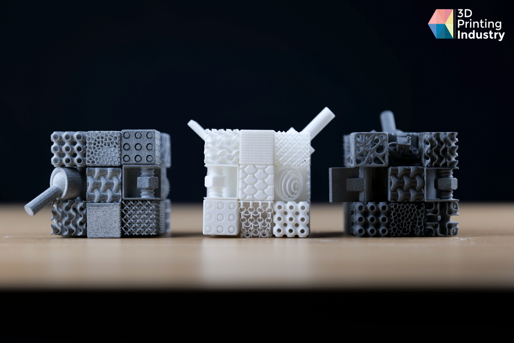
To further evaluate the printing capabilities of the three processes, we evaluated several physical 3D printed benchmarking tests. The first of these tests was a set of three torture cubes printed in PA12, which we had the pleasure of assembling ourselves. The design comprises several smaller cubes, each with a unique 3D printed feature such as a lattice geometry or a moving gear system.
The torture cube is a dynamic print test with a plethora of moving components, meaning it provides a great way to determine the differences in surface quality between the three technologies. In this case, we looked at how easy the assembly process was for each of the cubes, the overall fluidity of the cubes’ movements, and the detail resolution between the three technologies.
When it came time to assemble the HSS torture cube, the first six faces clipped in without much force at all. The corner pieces, which required sliding rather than clipping, were a little more difficult to slot into place due to friction, with some of them calling for the use of a screwdriver.
As for the 3D printed features, the HSS cube’s ball and socket joint did not work at all, the hinge worked but it was stiff, and the spring worked perfectly as intended. Furthermore, we encountered too much friction for the gear system to move at all, while the larger cube itself did rotate, albeit with some resistance.
Looking closer at some of the more intricate cube elements, we noticed that the HSS parts were the cleanest in terms of residual powder. In fact, we couldn’t find any loose powder in the cavities of the lattice geometries, so no additional post-processing was necessary.
Next up, we assembled the SLS torture cube. This time around, we faced more difficulty with the six clip-in faces due to the presence of excess powder in the joints. However, thanks to the smoother surface texture offered by SLS, the slide-in corner cubes were easier to assemble without as much friction.
Looking at the 3D printed features, the ball and socket joint did not work, the hinge did not work, but the spring worked just fine. Again, there was simply too much surface-to-surface bonding for the gear system to move at all, but the larger cube assembly was as smooth as can be. Overall, we were very impressed with the fluidity of the wider SLS assembly as it was the easiest to rotate.
Due to the presence of small volumes of residual Nylon powder in the lattice structures, we had to conduct some minor additional post-processing on the SLS build. This involved blowing out the cavities and manually shaking out the cube elements before assembly.
Finally, we assembled the MJF torture cube. Much like the HSS print, the first six faces clipped in with ease, but the relatively rough surface texture meant the slide-in corner pieces required some significant elbow grease.
Interestingly, the 3D printed features on this cube offered the best functionality of the three. The MJF assembly was the only one that had a working ball and socket joint, it had the smoothest hinge movement, and the spring bounced back as expected. However, the gear system failed to move again, owing to the grainy texture and unintentional bonding of the MJF surfaces. The ease of rotation was similar to that of the HSS build.
Much like the SLS cubes, we found small volumes of residual powder in the individual elements. Again, we had to perform some additional depowdering before assembling the MJF build, specifically by blowing out the cavities and manually shaking out the cubes.
When all was said and done, we could see that the HSS and MJF 3D printed cubes were noticeably grainier than their SLS counterparts, leading to rougher surface textures. In the case of the MJF cubes, we could also see the layer lines, meaning the HSS and SLS prints offered the best surface quality overall.
If we compare identical cubes between the three technologies, we notice that HSS offers the best detail resolution, delivering the finest edges, sharpest corners, and cleanest thin walls. Moving down, the SLS counterparts begin to get a little fuzzier, losing their sharpness and crispness somewhat. Finally, it’s the MJF variants that are the most visually blunt.
Benchmarking the technologies: industrial parts
To supplement the review, service providers also sent us four different industrial part designs 3D printed in PA12. Each of the models was 3D printed three times: once via HSS, SLS, and MJF. The following parts include a tubing element, a suspension prototype, a support bracket, and a general benchmarking model featuring sets of holes and towers. Much like the torture cubes, these 3D printed parts allow us to qualitatively assess the performance of the three processes.
Top – HSS, Middle – SLS, Bottom – MJF:
Looking at the tubing element, support bracket, and suspension prototype, we see once again that the SLS process is capable of achieving the smoothest surfaces. Similarly, the MJF parts were the only ones with layer lines visible to the naked eye, and voxeljet’s HSS 3D printer sat somewhere in the middle.
From the 3D printed benchmarking models, we could see that the HSS variant definitively had the finest geometric grooves and clearest writing – a testament to the process’ accuracy, suggesting that grain size really is more important than dpi when it comes to detail resolution. The SLS part was the only one to successfully fabricate all of the towers, however, with HSS and MJF missing the thinnest spike.
Interestingly, the holes on the MJF and SLS builds were printed as true circles (how they should be), whereas the HSS process yielded holes that were closer to ovals. However, HSS once again also delivered the finest edges and sharpest corners, while SLS and MJF were noticeably blunter.
Pricing and applications
How much does it cost for manufacturers to actually employ these polymer 3D printing technologies in their day-to-day operations? To answer this, we looked towards several 3D printing service providers.
To compare the pricing of HSS, MJF, and SLS, we requested instant quotes for four different 3D printable parts. We selected Nylon (PA12) as the material and averaged the quotes to provide a comprehensive pricing profile for each process.
Interestingly, it was HSS 3D printing that turned out to be the most cost-effective with an average part price of €15.82. MJF followed with an average part cost of €23.89 (+51.0{64d42ef84185fe650eef13e078a399812999bbd8b8ee84343ab535e62a252847}), while SLS proved to be the least cost-effective with an average cost of €27.50 (+73.8{64d42ef84185fe650eef13e078a399812999bbd8b8ee84343ab535e62a252847}).
Owing to the similarity of the technologies, HSS and MJF are actually similarly priced when considering initial costs, but there are several factors that ultimately make HSS more cost-effective. First of all, the size of the voxeljet VX1000 HSS allows for larger batches of parts to be printed, which reduces the cost per part in series production. HSS also makes use of just a single absorber fluid, whereas MJF relies on two fluids. This difference in material consumption further impacts running costs.
As far as applications go, both HSS and MJF provide a viable route to both functional prototyping and low-stress end-use production in sectors such as automotive and consumer goods. Use cases include electronics housings, connectors, brackets, covers, wiring clips, manufacturing guides, and ducting.
On the other hand, SLS, while pricier, lends itself to higher strength parts and is the only one of the three capable of processing high-performance engineering polymers like PEEK. As such, those in the market for high-strength end-use components will want to pay a premium to ensure they’re getting the mechanical properties they need for the job.
The verdict
So which of the polymer 3D printing technologies should you go for? Like many things in life, the answer is: it depends.
Inkjet technologies like HSS and MJF aren’t going to beat out SLS when it comes to part strength, but if you’re operating on a budget and the component in question won’t be under extreme loads, HSS might just be for you.
Interestingly, our testing also suggests that HSS lends itself to high-stiffness parts, whereas MJF offers greater ductility and elasticity, even when using identical materials. As such, HSS may be best used when deflection in a part needs to be minimized, while MJF should be employed in situations where bending and flexibility are requirements.
When it comes to dimensional precision, laser-based SLS 3D printing trumps both inkjet-based processes, but it’s HSS that exhibits the greatest repeatability. Again, this will depend on the use case but for many series production applications, repeatability is crucial in ensuring product reliability and meeting certain end quality goals.
Ultimately, we suggest conducting a comprehensive evaluation of costs, lead times, materials choices, and mechanical property requirements for specific parts and applications before opting for any one 3D printing technology.
Subscribe to the 3D Printing Industry newsletter for the latest news in additive manufacturing. You can also stay connected by following us on Twitter, liking us on Facebook, and tuning into the 3D Printing Industry YouTube Channel.
Looking for a career in additive manufacturing? Visit 3D Printing Jobs for a selection of roles in the industry.
Featured image shows a HSS torture cube. Photo by 3D Printing Industry.